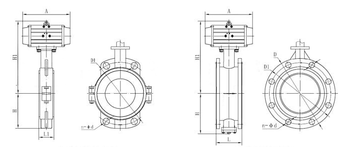
Pneumatic interfacing fluorine butterfly valve

Nominal Diameter:DN50~1000mm
Nominal Pressure:0.6~1.6MPa
Body Material : Ductile cast steel, cast steel, stainless steel +F46
Applicable temperature: -30~+70°C
Applicable medium: all kinds of strong corrosion Medium
I. Pneumatic lining fluorine butterfly valve products
Pneumatic lining fluorine butterfly valve adopts PTFE lined lining plate with spherical sealing surface. Pneumatic lining fluorine butterfly valve is easy to operate, with tight sealing performance and long service life; it can be used for quick cutting or adjusting flow. Pneumatic-lined PTFE butterfly valves are suitable for applications where reliable sealing and good adjustment characteristics are required. The valve body adopts split type, and the seal of the two ends of the valve shaft is controlled by the rotating base surface between the butterfly plate and the valve seat and the fluoro rubber; and the valve shaft is not in contact with the fluid medium in the cavity. Pneumatic lining PTFE butterfly valves are widely used in the transportation of liquids and gases (including steam) in various types of industrial pipelines. There are occasions where severe corrosive media are used, such as: sulfuric acid, hydrofluoric acid, phosphoric acid, chlorine, alkali, and king Water and other highly corrosive media.
Fully lined with PTFE (F4), polychlorotrifluoroethylene (F3) and polyfluorinated ethylene propylene (F46) fluorine plastic lining butterfly valves, with corrosion resistance, no leakage, long life and other advantages. Lined PTFE pneumatic butterfly valve is suitable for concentrated sulfuric acid, hydrochloric acid, nitric acid, hydrofluoric acid, aqua regia, various organic acids, strong acids, oxidizing medium or high-temperature olefinic sulfuric acid, high temperature concentrated acetic acid, alternating acid and alkali and various organic solvents and other Strong corrosive media.
Pneumatic Fluorine Butterfly Valve main features:
1, small and lightweight, easy to disassemble and repair, and can be installed in any position.
2, the structure is simple, compact, 90 ° turn quickly open.
3, the operating torque is small, effortless and light.
4. The flow characteristics tend to be linear and the regulation performance is good.
5, sealing material, anti-aging, corrosion resistance, applicable to a variety of media.
Second, the main technical parameters of pneumatic lined fluorine butterfly valve
1, valve body
| Body form | Straight cast butterfly valve |
| Nominal diameter | DN50~1000mm |
| Nominal pressure | PN1.0, 1.6 MPa |
| Flange standard | JIS B220, JB/T79, ANSI B16.5-1981, GB/T9113, HG20594-97, HG20618-97, etc. |
| Connection Type | Flange, clip type |
| Valve cover form | One-piece |
| Capping type | Gland compression type |
| Seal packing | V-type PTFE packing, flexible graphite packing |
2, valve trim
| Valve plate form | Vertical plate (butterfly) |
| Flow characteristics | Linear |
3, the executing agency
| Actuator model | GT Series, SR Series, AT Series, AW Series Single and Double Acting Pneumatic Actuators |
| Supply pressure | 400~700KPa |
| Air interface | G1/4"、G1/8"、G3/8"、G1/2" |
| 环境温度 | -30~+70℃ |
| 作用形式 |
单作用执行机构:气关式(B)--失气时阀位开(FO);气开式(K)--失气时阀位关(FC) 双作用执行机构:气关式(B)--失气时阀位保持(FL);气开式(K)-- 失气时阀位保持(FL) |
| 可配附件 | 定位器、电磁阀、空气过滤减压器、保位阀、行程开关、阀位传送器、手轮机构等 |
三、气动衬氟蝶阀主要性能指标
| 公称通径 | DN(mm) | 50~1600 | ||
|---|---|---|---|---|
| 公称压力 | PN(MPa) | 0.6 | 1.0 | 1.6 |
| 试验压力 | 强度试验 | 0.9 | 1.5 | 2.4 |
| 密封试验 | 0.66 | 1.1 | 1.76 | |
| 气密封试验 | 0.6 | 0.6 | 0.6 | |
| 适用介质 | 各类强腐蚀性介质 | |||
四、气动衬氟蝶阀零件材料
| 零件名称 | 材料 |
|---|---|
| 阀体 | (球墨铸钢、铸钢、不锈钢)+F46 |
| 蝶板 | (灰铸铁、球墨铸钢、铸钢、不锈钢及特殊材料)+F46 |
| 阀杆 | 2Cr13、不锈钢 |
| 填料 | O型圈、柔性石墨 |

外形连接尺寸
| 公称通径 DN(mm) | 50 | 65 | 80 | 100 | 125 | 150 | 200 | 250 | 300 | 350 | 400 | 450 | 500 | 600 | 700 | 800 | 900 | 1000 | |
|---|---|---|---|---|---|---|---|---|---|---|---|---|---|---|---|---|---|---|---|
| L | 90 | 90 | 100 | 115 | 130 | 140 | 150 | 250 | 270 | 290 | 310 | 330 | 350 | 390 | 430 | 470 | 500 | 550 | |
| L1 | 43 | 46 | 49 | 56 | 64 | 70 | 71 | 76 | 83 | 92 | 102 | 113 | 127 | 154 | 165 | 190 | 203 | 216 | |
| H | 法兰式 | 63 | 70 | 83 | 105 | 115 | 137 | 164 | 206 | 230 | 248 | 289 | 320 | 343 | 413 | 478 | 525 | 585 | 640 |
| 对夹式 | 63 | 70 | 83 | 105 | 115 | 137 | 164 | 206 | 230 | 248 | 289 | 320 | 343 | 413 | 478 | 525 | 585 | 640 | |
| n-φd | 4-18 | 4-18 | 8-18 | 8-18 | 8-18 | 8-22 | 12-22 | 12-26 | 12-26 | 16-26 | 16-30 | 20-30 | 20-33 | 20-36 | 24-36 | 24-39 | 28-39 | 28-42 | |
| H1 | 根据所配执行机构而定 | ||||||||||||||||||
| A | 根据阀门所需力矩而定,配置机型不同,外形尺寸也不相同 | ||||||||||||||||||
| D | 165 | 185 | 200 | 220 | 250 | 285 | 340 | 405 | 460 | 520 | 580 | 640 | 715 | 840 | 910 | 1025 | 1125 | 1255 | |
| D1 | 125 | 145 | 160 | 180 | 210 | 240 | 295 | 355 | 410 | 470 | 525 | 585 | 650 | 770 | 840 | 950 | 1050 | 1170 | |
Note: The dimensions in the table are without standard attachment data. In addition, due to possible changes in product innovation technology innovation parameters, please consult the company's technical department for the latest data.


 No.31011802002466

